Capital equipment investment decisions in glass fabrication are rarely straightforward — they involve complex trade-offs between initial purchase cost, operating cost, throughput capacity, format flexibility, floor space consumption, and the strategic value of the market access that specific capabilities enable. The cnc processing center investment decision is particularly multi-dimensional because the 4-in-1 multi-function platform competes not only with single-function alternatives on a cost-per-operation basis, but also with the combined capital cost, floor space, and integration complexity of purchasing multiple single-function machines to provide equivalent processing capability. When the complete investment picture is analyzed — including all direct and indirect costs, throughput implications, and strategic market positioning effects — the 4-in-1 CNC processing center consistently delivers a compelling return on investment for glass fabricators operating across multiple product segments.

Capital Cost: One Machine vs. Four

The most immediately visible element of the 4-in-1 CNC processing center investment decision is the comparison between the single machine's purchase price and the combined purchase price of four separate single-function machines providing equivalent capability — a straight edger, a shape edger, a drilling machine, and a waterjet. While the 4-in-1 machine's purchase price is higher than any individual single-function alternative, it is invariably significantly lower than the combined cost of four separate machines with comparable quality and control capabilities. Beyond the machine purchase price, the installation cost, electrical and compressed air connection costs, and commissioning costs of a single machine are dramatically lower than those of four separate machines — adding to the total capital cost advantage of the consolidated 4-in-1 solution. For glass fabricators working with constrained capital budgets, the 4-in-1 CNC processing center delivers the broadest processing capability per capital dollar invested.
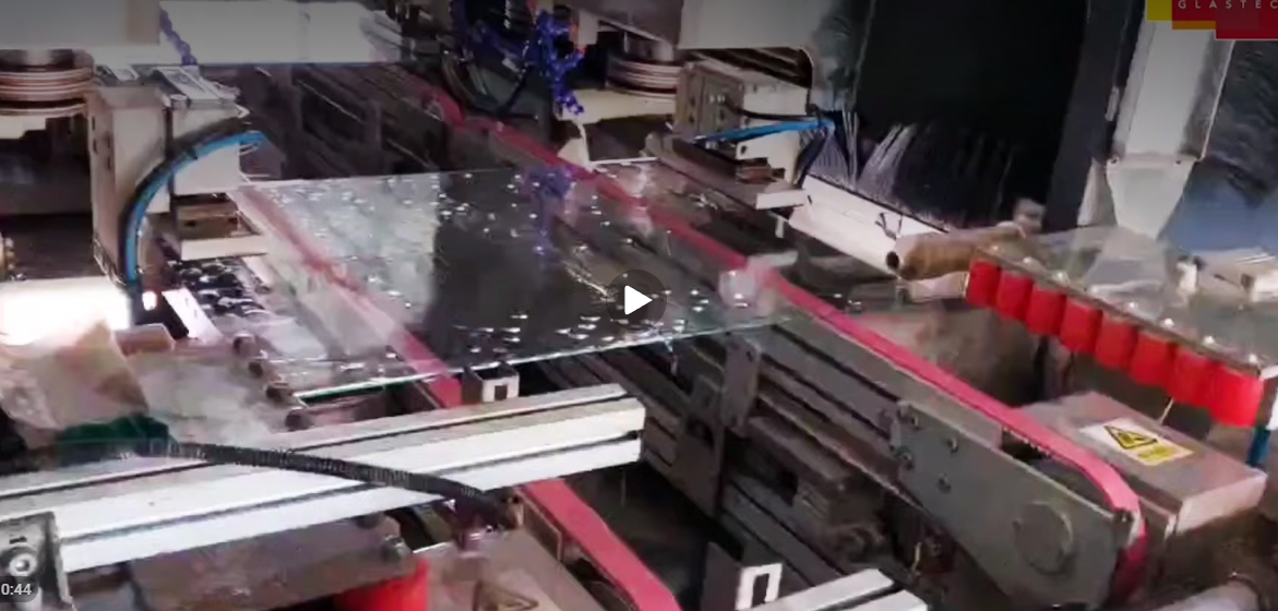
Floor Space and Factory Layout Advantages

Glass fabrication factories are typically constrained by floor space — particularly in urban industrial areas where property costs are high and expansion is difficult or impossible. A 4-in-1 CNC processing center occupies a fraction of the combined floor space of four separate single-function machines plus the inter-machine handling areas that separate machines require for glass panel transfer. This floor space saving translates directly into reduced factory rental or ownership cost, or alternatively into the ability to install additional capacity in the space freed by consolidating multiple single-function machines into a single processing center. For fabricators planning their first major processing equipment investment, or for established fabricators upgrading aging single-function equipment, the floor space efficiency of the 4-in-1 platform provides tangible commercial value beyond the direct machine cost comparison.

Reduced Handling and Improved Quality

Every glass handling operation — loading a machine, repositioning for a second operation, transferring between machines — is a risk event where the glass panel can be dropped, scratched, chipped at the edge, or thermally shocked by contact with cold metal surfaces. Consolidating four processing operations into a single machine with one loading and one unloading cycle reduces the handling risk events for each panel by approximately 75% compared to sequential processing on four separate machines. This handling reduction directly reduces the breakage and scratch damage rates that inflate the cost of goods sold in glass fabrication operations with multiple single-function machines, and improves finished product quality by eliminating the edge chips and surface scratches that handling operations introduce between processing steps. MAC GLASTECH's 4-in-1 CNC processing center is specifically designed for integration into automated glass handling lines — with automatic loading tables, turnover systems, and output conveyors that minimize manual glass handling throughout the complete processing sequence.
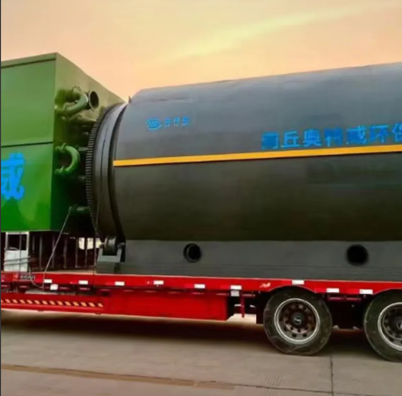

The transition from manually operated to fully automatic pyrolysis machine technology represents one of the most significant recent advances in waste-to-fuel processing — and for operators managing large-scale commercial facilities, the economics of automation can be transformative. AOTEWEI's 100KG to 50 TPD fully automatic continuous engine fuel oil refinery and pyrolysis plant series exemplifies this automation capability: from feedstock delivery through reactor operation to product dispatch, the system's PLC control architecture manages process variables, executes scheduled sequences, and responds to process deviations with minimal human intervention, enabling a small, multi-skilled operating crew to manage a large-throughput operation with the reliability and consistency that manual systems cannot sustain across long operating shifts.

The economic benefits of fully automatic pyrolysis machine operation flow from three principal sources. First, labour cost reduction: an automated system can be operated by two to three operators per shift compared to five to eight required by a manually intensive batch operation of equivalent throughput, providing a direct reduction in the largest operating cost category for most pyrolysis machine businesses. Second, consistency improvement: automated process control maintains temperature profiles, residence times, and operating conditions within tighter tolerances than manual operation allows, producing more consistent fuel oil yield and quality across every operating shift. Third, safety enhancement: automated emergency response systems — including automatic gas isolation valves, reactor pressure relief, and burner shutdown on process deviation — respond in milliseconds to developing safety situations, eliminating the response lag that creates the highest-risk scenarios in manually operated systems. The combination of lower labour cost, higher product consistency, and improved safety record creates a facility that is both more profitable and more attractive to investors, insurers, and regulatory authorities than its manually operated equivalent.

pyrolysis machine fully continuous continuity pyrolysis Patented Environmentally Friendly Continuous Cracking Reactors

Components of Full Automation in a Pyrolysis Machine System

Full automation in a pyrolysis machine system encompasses the automated management of every stage of the pyrolysis process rather than simply the reactor heating and temperature control that even basic systems include. In AOTEWEI's fully automatic continuous pyrolysis machine, automation covers: feedstock pre-processing scheduling (automatic shredder start/stop and conveyor speed control based on downstream hopper level sensors); feed rate management (automatic adjustment of feed screw speed based on reactor load sensors and temperature feedback); multi-zone temperature control (independent PID control of each heating zone to maintain the designed temperature profile against feedstock variation); condensation train management (automatic adjustment of cooling water flow to maintain optimal condensation temperatures at each stage); product transfer (automatic transfer of condensed fuel oil from condensation receivers to storage tanks based on level sensors); carbon black discharge (automatic operation of the sealed discharge screw and conveyor to maintain reactor bed depth within design limits); and process alarm management (automated response sequences for over-temperature, over-pressure, feed interruption, and product backup conditions). This comprehensive automation scope enables reliable, consistent operation with minimal operator intervention and creates the operational data record that supports continuous improvement and regulatory compliance reporting.

Integration of the Fully Automatic Pyrolysis Machine with Downstream Refining

The fuel oil produced by a fully automatic pyrolysis machine can be marketed directly as industrial heavy fuel oil, or it can be further refined through a distillation process to produce lighter, higher-value petroleum products including diesel fuel and light fuel oil. AOTEWEI offers integrated pyrolysis and distillation system packages that combine the fully automatic pyrolysis machine with a continuous or batch distillation unit, enabling operators to produce market-grade diesel or light fuel oil from waste tyre and plastic feedstock in a single integrated facility. The integration of pyrolysis and distillation in one facility — designed as a unified system rather than two separate plants — enables significant energy efficiency improvements through waste heat sharing between the pyrolysis and distillation stages, and reduces total capital cost compared to purchasing and installing the two systems independently. For investors seeking the highest possible value per tonne of processed feedstock, the fully integrated automatic pyrolysis and refining system from AOTEWEI represents the peak expression of waste-to-value technology in the current market.

Pet care professionals and experienced dog and cat owners alike agree: the quality of the pet ear drop bottle used for at-home ear treatment profoundly affects both the safety of the administration process and the stress level experienced by the animal. A bottle that delivers consistent, controlled drops without waste or mess allows treatment to be completed quickly and calmly — two qualities that are critically important in establishing positive associations with the treatment process and ensuring the animal's ongoing cooperation through a multi-week treatment course.

Safety Features That Protect Both Pet and Owner

The primary safety concern in pet ear drop bottle design is the prevention of tip-related ear canal injury. A rigid, inflexible tip represents a potential injury hazard if the animal moves suddenly during administration — a common occurrence even in well-trained pets who become startled by an unexpected sound or movement. Soft polyethylene tips that flex on contact provide a meaningful safety margin in this scenario: the tip deforms rather than injuring the ear canal tissue. Additionally, a tip length calibrated for the typical ear canal depth of the target species — longer for large dogs, shorter for cats and small breeds — prevents over-insertion that could traumatise the deeper ear structures.

Reducing Stress Through Efficient Technique

Veterinary behavioural research consistently shows that the duration of a treatment procedure is one of the strongest predictors of animal stress during that procedure. Shorter procedures create less sustained anxiety than longer ones, even when the discomfort per unit of time is similar. This has direct implications for pet ear drop bottle design: a bottle that allows the dose to be dispensed quickly, cleanly, and without repositioning delivers the treatment in a shorter total time window, reducing the cumulative stress of the interaction. Every design element that prevents interruptions — secure one-handed grip, reliable flow without squeezing interruptions, no dripping after dose delivery — contributes to the efficiency that reduces treatment time and associated stress.

60ml Plastic Eye Wash Cleaning Bottle for Cats and Dogs Squeeze Container — Santong Plastics (santongplastics.com)

Building Positive Treatment Associations

For animals undergoing repeated ear treatments — particularly those with chronic ear conditions requiring ongoing maintenance — the emotional association built through early treatment experiences shapes the animal's cooperation for all subsequent sessions. A calm, efficient, mess-free treatment delivered with a well-designed bottle, followed immediately by a reward, builds a positive association. A stressful, prolonged procedure resulting from a dripping bottle, missed doses requiring repositioning, or restrained animal struggling against an uncomfortable tip creates a negative association that escalates with each session. Investing in a quality pet ear drop bottle is therefore not merely a convenience choice but a welfare decision with compounding impact across the animal's treatment history.

Sourcing Quality Pet Ear Drop Bottles

Pet product manufacturers, veterinary compounders, and pet care brands sourcing bottles for ear care formulations should prioritise suppliers with documented pharmaceutical-grade material credentials, precise tip manufacturing tolerances, and quality management certification appropriate for veterinary product packaging. Santong Plastics' dedicated pet ear drop bottle range — produced to FDA and ISO quality standards with over 25 years of plastic packaging manufacturing experience — provides the consistency, material safety, and dimensional precision that quality-oriented pet care brands require in their packaging supply chain.


As global consumer consciousness around environmental sustainability continues to deepen, the bamboo fan has transitioned from being simply a traditional craft product to being an active sustainability statement — a product whose choice of material communicates the buyer's values as clearly as any other aspect of its design or branding. Bamboo's extraordinary environmental profile, combined with its natural beauty, structural versatility, and rich cultural heritage, makes it the most compelling natural material choice in the contemporary custom fan market for any buyer who wants their product to be both genuinely beautiful and genuinely responsible. Understanding bamboo's environmental credentials, cultural significance, and aesthetic possibilities is the foundation for sourcing bamboo fans that make a genuine impact — commercially, aesthetically, and ethically.

Bamboo's status as the world's fastest-growing plant gives it an environmental advantage over virtually every other structural material used in fan production. Moso bamboo — the species most commonly used for fan rib production in China's craft manufacturing sector — reaches full structural maturity in just three to five years, compared to 20–100 years for the hardwoods used in high-quality wooden fan production. This dramatically shorter growth cycle means that bamboo can be harvested at a sustainable rate without depleting forest stocks, and that bamboo plantations can recover and regenerate within years rather than decades after harvesting. The root system of harvested bamboo plants remains intact after cutting, enabling the plant to regenerate immediately from the existing root mass — meaning that bamboo cultivation does not require the soil disruption and reseeding that timber harvesting demands. These characteristics have made bamboo one of the most widely certified sustainable materials in global craft and manufacturing sectors, with chain-of-custody certifications available for bamboo sourced from responsibly managed plantations in China's primary bamboo-growing regions.

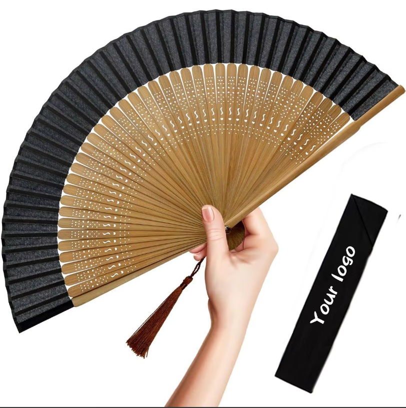
Custom Logo Plain Color Chinese Hand Fan Fabric Silk Bamboo Folding Hand Fan

The Aesthetic Appeal of Bamboo in Modern Fan Design

Beyond its environmental story, bamboo's aesthetic qualities make it an inherently beautiful material for hand fan construction. The natural colour of mature Moso bamboo ribs — a warm, honey-toned gold with subtle darker grain lines — provides a visually rich organic backdrop that enhances the fan leaf's design rather than competing with it. As bamboo ages and is handled, its surface develops a deeper patina that adds character and warmth to the fan's appearance — a quality associated with natural materials that synthetic alternatives simply cannot replicate. The slight variation in grain pattern between individual ribs means that no two bamboo fans are ever completely identical, giving each fan a degree of uniqueness that adds to its value as a handcrafted natural product.

Contemporary designers working with bamboo fans have moved well beyond traditional interpretations to create products that combine bamboo's natural character with modern design aesthetics in ways that resonate strongly with current market trends. Minimalist bamboo fans with unfinished natural ribs and simply printed white paper leaves appeal to Japandi aesthetic sensibilities. High-contrast bamboo fans with lacquered black-stained ribs and dramatically printed leaves suit luxury fashion and high-end event markets. Natural bamboo fans with pressed flower and botanical print leaves connect with the growing market for craft products that celebrate the beauty of the natural world. Yiwu Qunsen's design team and production capabilities support all of these contemporary bamboo fan design directions, enabling buyers to create bamboo fan products that are thoroughly of the moment in their aesthetic positioning while retaining the natural material authenticity that gives bamboo fans their enduring market appeal.

Wholesale Bamboo Fan Sourcing: Why Yiwu Is the Right Origin

Yiwu, Zhejiang Province, China, has been at the centre of the global small commodity export trade for over three decades, and the city's concentration of specialist craft manufacturers, raw material suppliers, and export logistics infrastructure makes it the most efficient sourcing location in the world for wholesale bamboo fan products. Yiwu Qunsen Craft, located in Yiwu and serving global buyers from markets across Europe, North America, Asia, the Middle East, and beyond, leverages this ecosystem to source the highest quality bamboo raw materials, apply the most skilled craft production techniques, and deliver finished bamboo fan products to global buyers at the competitive prices that China's manufacturing scale enables. For wholesale bamboo fan buyers building their first import programme or expanding an existing one, the combination of Yiwu Qunsen's product expertise, manufacturing quality, and export experience makes them the partner of choice in the global bamboo fan supply market.

Building a complete lower body training zone requires a clear understanding of how each category of leg fitness equipment contributes to the overall training programme — what muscle groups each machine targets, how it complements or overlaps with other machines in the zone, and what capacity and quality specifications distinguish commercial-grade from residential or light-commercial products. This guide provides the essential knowledge base for selecting and specifying a comprehensive commercial lower body equipment suite.

Leg Press Machine: Foundation of the Lower Body Zone

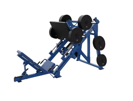
The leg press is the highest-priority machine in any commercial lower body training zone. It is the primary tool for loading the quadriceps, hamstrings, and glutes through a squat-pattern movement — providing the compound lower body stimulus that is most directly transferable to functional athletic performance. Available in two primary configurations — seated (horizontal press) and sled (45-degree incline press) — the leg press should be selected based on the expected user profile and space availability. The seated leg press provides a more upright torso position that reduces lumbar spine involvement, making it the preferred configuration for members with lower back sensitivity. The 45-degree sled press allows heavier loading and a greater range of motion for experienced trainers.

SDCX Multi-Functional Steel Leg Press Machine with Smith Trainer — Comprehensive Leg Fitness Equipment Combining Leg Press, Squat and Multi-Function Capability for Commercial Facilities

Leg Extension Machine: Quadriceps Isolation

The seated leg extension machine targets the quadriceps in isolation — the most important single-muscle-group isolation movement in lower body programming. By eliminating the hip movement component that makes compound exercises multi-joint, the leg extension loads the quadriceps exclusively through the knee extension movement, producing targeted hypertrophy and strength gains that compound movements alone cannot achieve. When purchasing a commercial leg extension machine, prioritise adjustability of the shin pad position, back pad recline angle, and weight stack increment. The smallest available weight increment determines the minimum resistance progression step — smaller increments enable finer progression management for beginners and smaller athletes, improving the machine's utility across the member spectrum.

Thigh Adductor Machine: Inner Thigh and Hip Stability

The thigh adductor machine is the dedicated tool for developing the adductor muscle group — the inner thigh muscles responsible for pulling the leg toward the body's midline and for stabilising the knee during squatting and landing movements. This machine is particularly important for female athletes, where adductor and hip abductor strengthening is a key component of ACL injury prevention programmes, and for athletes in all disciplines where lateral agility and knee stability are performance determinants. The thigh adductor machine should feature adjustable starting position — the width between the thigh pads at the start of the movement — to accommodate users of different flexibility levels and to allow progressive range of motion development as the user's adductor flexibility improves.

Leg Curl Machine: Posterior Chain Development

The leg curl machine — available in lying, seated, and standing configurations — is the primary dedicated tool for hamstring development. The lying leg curl is the most widely deployed configuration in commercial facilities, providing a stable, controlled movement path that most users can learn quickly. The seated leg curl offers the advantage of a stretched hamstring starting position — due to the hip flexed position — that increases the muscle's excursion through the movement and may produce superior hypertrophy stimulation. The standing leg curl addresses the hip extension function of the hamstring simultaneously with knee flexion, providing a complementary stimulus to the supine or seated configurations. A comprehensive commercial lower body zone should include at minimum one leg curl configuration — and ideally two — to provide variety and progression options for members who train hamstrings frequently in their programmes.

While food packaging represents the largest single application market for bopet film, its exceptional property profile — high strength, thermal stability, electrical insulation, optical clarity, and surface processability — has made it indispensable across a remarkable range of non-packaging applications in electronics, optics, photovoltaics, and industrial manufacturing. Understanding these technical applications illuminates why BOPET film is classified as a structural material rather than merely a packaging commodity.

Electrical and Electronic Insulation

BOPET film's excellent electrical insulation properties — volume resistivity exceeding 10¹⁵ Ω·cm and dielectric strength of approximately 180 kV/mm — combined with its thermal stability make it a critical component in numerous electrical and electronic applications. Capacitor dielectric: BOPET film between 3 and 12 microns is used as the dielectric layer in film capacitors for power electronics, motor drives, and consumer electronics, where its electrical and thermal stability under high-voltage stress is essential. Motor and transformer slot insulation: BOPET film laminated with other insulation materials provides the primary electrical insulation in rotating machine windings and transformer coil assemblies. Flexible circuit substrates: the combination of BOPET's dimensional stability, electrical insulation, and surface processability supports flexible circuit board applications in consumer electronics and medical devices.

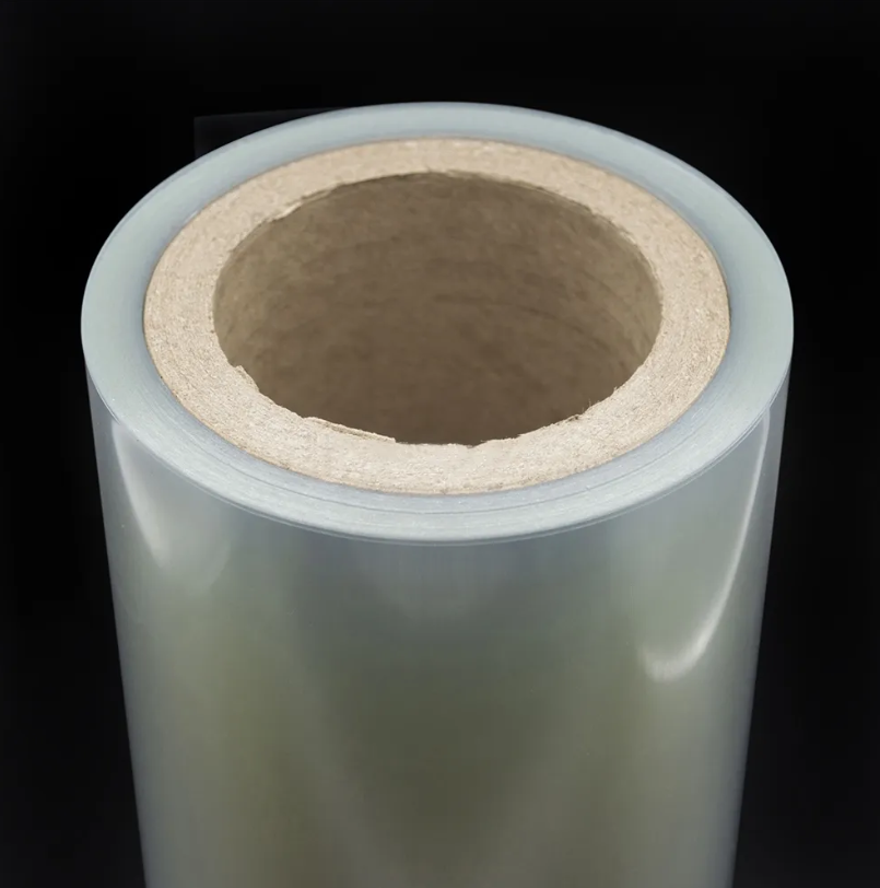
Clear BOPET Film Roll — Electronics & Industrial Grade — Anhui Ocan Material (ocanpetpvc.com)

Optical Display Applications

The display technology industry is one of the most demanding applications environments for BOPET film, requiring exceptional optical uniformity, dimensional stability under thermal cycling, and surface quality compatible with precision coating processes. Brightness enhancement films (BEF) used in LCD backlighting systems use BOPET film as the substrate for micro-prism structures that redirect light toward the viewer, improving display brightness efficiency. Diffusion films that scatter backlight uniformly across the display panel use BOPET film with controlled haze surfaces. Anti-reflection and anti-glare coatings applied to BOPET film protect display surfaces in consumer electronics, medical instruments, and industrial control panels. The uniformity requirements for these display applications are among the most demanding in any BOPET film application — making optical display grade BOPET a premium product tier within the overall film market.


Solar Energy and Photovoltaic Backsheets

Solar photovoltaic (PV) modules use BOPET film as the primary component of back-sheet structures — the weather-resistant outer layer that protects the module's electrical components from moisture ingress, UV degradation, and physical damage over the module's 25-year design life. PV backsheets typically consist of a fluoropolymer outer layer (for UV and weather resistance), a BOPET film core (for mechanical strength, moisture barrier, and electrical insulation), and an inner adhesive layer for bonding to the encapsulant. The BOPET core layer's dimensional stability under the thermal cycling of daily sun exposure, its moisture barrier contribution, and its electrical insulation performance are all critical to long-term PV module performance and safety.

Industrial Tape and Protective Film Applications

BOPET film serves as the substrate for high-performance adhesive tapes used in electronics manufacturing, automotive assembly, and construction applications where dimensional stability, temperature resistance, and mechanical strength are required. As a protective film substrate, BOPET provides the strength, stiffness, and surface quality needed for temporary surface protection applications in glass, metal, and plastic panel manufacturing. The combination of dimensional stability, processability for adhesive coating, and mechanical performance make BOPET film the tape substrate of choice wherever performance requirements exceed the capabilities of polyolefin alternatives.

Large-scale paper cup manufacturing operations — producing hundreds of millions of cups per year for national retail chains, institutional catering contracts, or multinational brand owner supply agreements — require a fundamentally different specification approach to double wall paper cup machine investment than the considerations that apply to startup and SME-scale producers. At volume, the specifications that matter most are not the machine's peak output speed in ideal conditions but its sustained reliability across extended production campaigns, its format changeover efficiency across a diverse SKU range, its integration with automated material handling and packaging systems, and its long-term serviceability with documented spare parts availability and technical support response commitments.

Reliability Engineering for High-Volume Operations

Large-scale production operations cannot tolerate the mechanical unreliability that is acceptable in low-volume specialty production where a few hours of downtime per week has minimal financial impact. At 10 million cups per week, one hour of unplanned machine downtime represents approximately 100,000 lost cups and potentially missed delivery commitments to retail chain customers who operate on precise just-in-time inventory management principles. Double wall paper cup machines specified for large-scale production must be engineered for maximum mechanical reliability through generous duty-cycle ratings on all motion components, predictive maintenance capability through vibration monitoring and process parameter trending, rapid access to wear components through well-designed maintenance access panels, and comprehensive spare parts kits maintained on-site for all high-wear items. Wenzhou Qichen Trading specifies maintenance access design and spare parts availability as standard considerations in large-scale machine quotations.


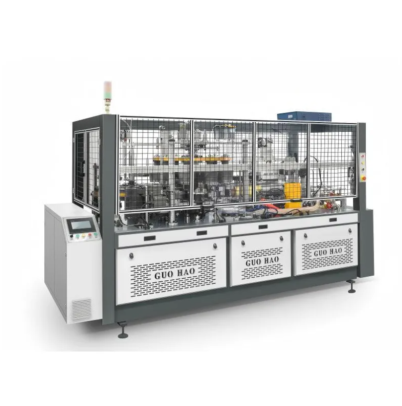
G-200 Automatic Paper Bucket Machine| Source: wzqichen.com

Multi-Machine Line Design for Capacity Scaling

Large-scale double wall cup manufacturers rarely rely on a single machine for their total production capacity — the concentration of all production on one machine creates unacceptable supply chain risk if that machine experiences an extended mechanical failure. The preferred configuration for large-scale operations is a multi-machine production hall with several identical or complementary double wall cup machines running in parallel, sharing common raw material feeding infrastructure, quality inspection systems, and downstream packaging equipment. This configuration provides capacity redundancy — allowing production to continue at reduced capacity during any single machine's planned maintenance or unplanned downtime — while also enabling format-specific scheduling where different cup sizes run simultaneously on different machines for maximum production flexibility. Machine standardization within the fleet — purchasing all machines from the same manufacturer to a common specification — simplifies operator training, reduces spare parts inventory complexity, and enables machine-to-machine quality comparison that facilitates root cause analysis of any production quality issues.

Technical Support Contracts for Business Continuity

For large-scale operations where machine downtime has immediate revenue and customer relationship consequences, formal technical support contracts with the machine supplier are a practical business continuity investment that justifies their cost through documented downtime reduction. A comprehensive technical support contract from Wenzhou Qichen Trading includes guaranteed response time commitments for remote diagnostic support, priority access to spare parts from pre-agreed inventory, scheduled preventive maintenance visits by factory-trained service engineers, and access to machine control software updates that improve performance and address field-identified reliability issues. These contractual commitments transform the supplier relationship from a transactional equipment purchase into a sustained technical partnership that serves the large-scale manufacturer's long-term production reliability objectives.

Achieving a stable pigment dispersion in a water-based coating formulation is a multidisciplinary technical challenge that draws on colloidal chemistry, polymer science, surface physics, and applied rheology. The challenge is fundamentally about maintaining the pigment particles in a well-separated, uniformly distributed state within a complex aqueous medium — resisting the multiple physical and chemical forces that drive particles toward agglomeration and sedimentation. Understanding the science behind dispersion stability helps formulators make better decisions about dispersant selection, pH management, and formulation architecture that translate directly into better performance and longer shelf life in commercial products.

Colloidal Stability Mechanisms: Electrostatic and Steric

Two primary mechanisms stabilise colloidal dispersions against particle aggregation. Electrostatic stabilisation relies on the development of a surface charge on the pigment particles — either inherent to the pigment surface chemistry or induced by the adsorption of ionic dispersant molecules — that creates repulsive forces between approaching particles. The zeta potential of a dispersion, measured by electrophoretic light scattering, quantifies the magnitude of this electrostatic repulsion: values more negative than -30 mV or more positive than +30 mV are generally associated with good electrostatic stability. Steric stabilisation relies on polymer chains — either attached to the particle surface through dispersant anchor groups or present in the continuous phase — that create a physical barrier between approaching particles, preventing the close approach distances where van der Waals attraction would drive aggregation.


Sunmun YC Series Water-Based Pigment Dispersion — Engineered for Versatility Across Water-Based Industrial Applications with Outstanding Colloidal Stability and Color Consistency

pH Management and Ionic Strength Effects

The pH of the aqueous medium profoundly affects the electrostatic stabilisation of water-based pigment dispersions. Most water-based coating dispersions are formulated at pH values between 7.5 and 9.5 — a range that provides sufficient ionisation of dispersant carboxylate groups to generate adequate surface charge for electrostatic stabilisation, while avoiding the corrosive effects of extreme alkalinity on metal packaging and application equipment. pH drift during storage — often caused by CO₂ absorption from atmospheric air or by binder hydrolysis — can shift the dispersion into a less stable pH region and cause slow agglomeration that manifests as increased viscosity or settling over time. Buffering the dispersion formulation with appropriate pH-adjusting agents maintains the design pH throughout the product's shelf life and prevents stability loss during storage.

Influence of Electrolytes on Dispersion Stability

Dissolved salts and electrolytes in the continuous phase of a water-based dispersion compress the electrical double layer around pigment particles — reducing the range of electrostatic repulsion and bringing particles closer to the aggregation-inducing van der Waals attraction energy. Hard water, with its elevated calcium and magnesium ion content, is a particularly common source of electrolyte-induced stability problems in water-based dispersions. Formulating dispersions using deionised water, incorporating electrolyte-tolerant steric dispersants that maintain their stabilising function in the presence of multivalent ions, and specifying the acceptable water hardness range for end-use thinning are all approaches used by experienced formulators to manage electrolyte sensitivity in commercial water-based dispersion products.

Accelerated Stability Testing Protocols

Commercial water-based pigment dispersions are expected to maintain their performance characteristics for twelve to twenty-four months under typical storage conditions. Verifying this shelf life through real-time storage testing would require development programmes of one to two years per product — incompatible with the pace of commercial product development. Accelerated stability testing protocols — including elevated temperature storage (typically 50°C for four weeks as an accelerant for six-month real-time stability), freeze-thaw cycling, and mechanical stability testing through high-speed centrifugation — provide faster indicators of stability that correlate with real-time shelf life when the protocols are properly validated. Using these accelerated protocols as the primary stability qualification methodology allows dispersion manufacturers to release new products with confidence in their shelf life performance within commercially acceptable development timelines.

Selecting a multi-angle workshop fitting machine for your fabrication facility requires evaluating a set of specifications that determines both the range of fittings you can produce and the quality you can achieve. This buying guide covers the essential specifications, key features, and selection considerations that distinguish excellent multi-angle workshop fitting machines from marginal ones.

Maximum Pipe Diameter and Welding Range

The welding range — the minimum and maximum pipe OD the machine can accommodate — is the primary selection driver. The WDF315–1600 series from Hangzhou Welding Technology offers models from WDF315 (up to 315mm) through WDF1600 (up to 1600mm), each covering the ranges most relevant to specific market segments. Ensure the machine's maximum diameter exceeds the largest pipe size you anticipate fabricating in the next five years — upgrade costs later are always higher than buying the right capacity initially. Also verify the minimum welding diameter: some large-capacity machines have minimum diameters that exclude smaller fittings commonly needed for branch connections or service connections.

Heating Plate Performance

The PTFE-coated removable heating plate is the component most critical to welding quality. Evaluate maximum temperature capability (270°C is the professional specification), temperature uniformity across the plate surface, PTFE coating quality, and the ease of plate removal and replacement. A heating plate with inconsistent temperature distribution creates uneven plasticization at the joint face — the most common cause of incomplete fusion and weak joint zones in workshop fabrication. The removable plate design of the WDF series allows complete plate surface inspection and replacement without machine disassembly, supporting maintenance practices that keep fusion quality consistent throughout the plate's service life.

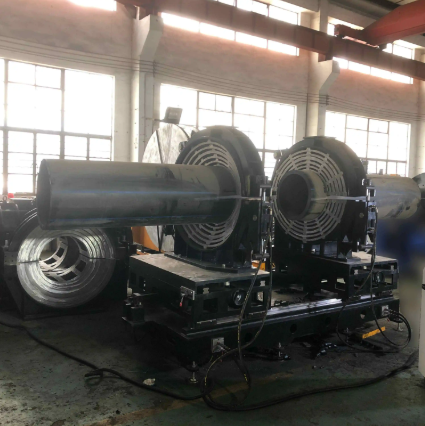
 WDF315——1600 Multi-angle welding machineHangzhou Welding Technology (hdpeweldingtech.com)

Timer System and Process Documentation

A dual-channel independent timer system — separately recording heat soaking time and cooling time — is essential for quality-assured multi-angle workshop fitting machine operation. Single-channel timers that measure total cycle time cannot verify that the critical heating soak phase was correctly completed before fusion pressure was applied, which is the most important timing quality parameter. The WDF315–1600's separate two-channel timer provides the process discipline and documentation capability that distinguishes professional fitting production from casual fabrication work. For facilities whose clients require production documentation, this timer data becomes part of the quality record for each fitting produced.

Hydraulic System Power and Pressure Control

Match the machine's hydraulic system power and maximum operating pressure to your pipe wall thickness requirements. Thicker-walled pipe (lower SDR) requires higher fusion force to achieve the correct bead formation pressure. The WDF series hydraulic units range from 0.75 kW (WDF315) through 7.5 kW (WDF1200 and WDF1600), reflecting the increasing force requirements for larger diameter pipes. The adjustable pressure range (0–6 MPa on all WDF models) provides sufficient flexibility for all standard PE pipe wall thicknesses. Verify that the hydraulic system's pressure stability under load is consistent — pressure fluctuation during the fusion phase compromises joint quality by producing uneven fusion bead geometry.

Certifications, Warranty and Support

Before finalising a multi-angle workshop fitting machine purchase, verify CE marking and ISO 9001 certification, confirm warranty terms (2 years is the Hangzhou Welding Technology standard), and evaluate the supplier's technical support capability including spare parts availability, remote technical assistance, and operator training provisions. The total cost of ownership over a 5-10 year machine life is strongly influenced by these support factors — a machine that cannot be quickly returned to service after a component failure represents a significantly greater cost than a more expensive but better-supported alternative. Hangzhou Welding Technology's established global service network and documented technical support programs provide the post-purchase confidence that professional equipment buyers require.

The debate between manual and electric toothbrushing has been comprehensively resolved by two decades of rigorous clinical research — and the verdict strongly favours the rotating electric toothbrush for adults and children who prioritise measurable oral health outcomes over habit and preference. The most compelling evidence comes from the Cochrane systematic review referenced by dental associations worldwide, which analysed randomised controlled trials comparing rotating-oscillating electric toothbrushes with manual toothbrushes and found that the electric option reduced plaque by an additional 21% at one month and 11% at three months, and reduced gingivitis by an additional 6% at one month and 17% at three months. These are not marginal improvements — they represent clinically significant differences in the rate of periodontal disease progression, decay incidence, and the overall trajectory of a patient's long-term dental health. For the significant proportion of patients for whom manual brushing technique is suboptimal — including the elderly, those with limited manual dexterity, orthodontic patients, and children — the improvement margin is often even greater.

The mechanism by which rotating electric toothbrushes achieve superior plaque removal comes down to the intersection of two factors: consistency and mechanics. Manually, most adults brush for less than the recommended two minutes, focus disproportionately on easily accessible tooth surfaces at the expense of posterior and lingual surfaces, and apply variable pressure and technique that produces inconsistent results. A rotating electric toothbrush with a built-in two-minute timer and a quadrant-change indicator removes the time consistency problem entirely, ensuring that every brushing session meets the minimum duration for effectiveness. The oscillating-rotating brush head's consistent mechanical motion then removes the technique variability problem — effective plaque disruption occurs on every tooth surface that the brush head contacts, regardless of the user's manual dexterity, arm strength, or brushing angle.

Smart Electric Toothbrush Adult Rotating Toothbrush Travel 5 Modes IPX7 Rechargeable Automatic Electric Toothbrush

Pressure Sensitivity in Rotating Electric Toothbrushes: Protecting Enamel and Gums

One of the most important protective features in advanced rotating electric toothbrush designs is a pressure sensor that alerts the user when they are brushing too hard. Over-brushing — applying excessive force between the brush head and tooth surface — is a common technique error that, when habitual, causes enamel abrasion (measurable thinning of the tooth's outer protective layer) and gum recession (the gradual pulling back of gum tissue from the tooth neck, which exposes sensitive root surfaces and creates aesthetic and sensitivity concerns). Many users press harder with their electric toothbrush believing that increased pressure improves cleaning — when in fact the brush's mechanical action requires only light contact to achieve its full cleaning effect, and excess pressure actively reduces cleaning efficiency by splaying the bristles and reducing their per-tooth contact geometry.

Charmhome's rotating electric toothbrush designs incorporate user-facing pressure management features that help users develop the correct light-touch brushing habit. Visual or tactile feedback systems — LED colour changes, vibration pattern alterations, or motor speed reduction — activate when the user applies force above the recommended threshold, providing immediate, actionable feedback that gradually trains the user toward the correct brushing pressure. This training effect, compounded over months of daily use, delivers a permanent improvement in brushing technique that benefits the user's enamel and gum health for life. For dental professionals recommending electric toothbrush products to patients with existing enamel wear or gum recession, pressure feedback capability is a clinical selection criterion that makes the Charmhome rotating electric toothbrush range a particularly appropriate recommendation for the patients most at risk from habitual over-brushing.

Environmental Credentials of the Modern Rotating Electric Toothbrush

Environmental sustainability has become an important purchase criterion for a growing segment of oral care consumers, and the rotating electric toothbrush's environmental profile — when assessed across its full lifecycle — is more favourable than the disposable manual toothbrush's in several important dimensions. A rotating electric toothbrush handle that lasts five or more years, with only the brush head replaced every three months, generates significantly less plastic waste than the four manual toothbrushes per year that the same user would otherwise discard in their entirety. Charmhome's commitment to designing rotating electric toothbrush handles for durability — using robust handle materials, quality motor components, and reliable charging systems that extend product service life — contributes directly to this sustainability advantage by ensuring that the one-time handle investment achieves its maximum useful life before requiring replacement.

ample Text

Modern telecommunications networks — spanning fiber optic backbones, copper access loops, wireless tower feeder cables, and data center structured cabling infrastructure — depend on reliable cable connections that maintain signal integrity and physical protection across service lives measured in decades. The heat shrinkable sleeve is a fundamental component in telecommunications cable management at multiple levels of the network, from the individual fiber optic splice protection sleeve that protects a single fusion-welded glass fiber to the large-diameter environmental protection sleeve that seals an entire fiber distribution point against weather and moisture ingress in an outdoor terminal cabinet or pole-mounted closure.

Fiber Optic Splice Protection: The Critical Connection Point

Every fusion splice in a fiber optic network represents a point of mechanical vulnerability — the re-joined glass fiber is microscopically thin, fragile, and subject to breakage if bent beyond its minimum bend radius or subjected to axial tension loads. Fiber optic splice protection sleeves — miniature heat shrinkable tubes pre-loaded with a stainless steel or ceramic reinforcing rod — provide the mechanical reinforcement and protective enclosure that prevents fiber breakage at the splice point. The sleeve is positioned over the fiber before fusion splicing, then slid over the completed splice and heat-activated to grip both sides of the fusion junction and the reinforcing rod, creating a rigid protective structure that maintains the fiber in a protected, straight configuration regardless of the mechanical handling and movement that a fiber optic splice closure experiences during installation, subsequent cable maintenance, and network reconfiguration over decades of service life.

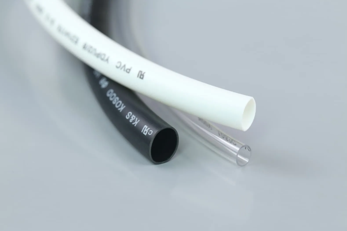
Type 1 PVC tube, 0.3mm-2.0mm Wall, UL Listed, Electrical Raceway

Cable Identification in Data Centers: Color and Labeling

In high-density data center environments where thousands of identical-looking patch cords connect servers, switches, storage arrays, and network appliances across rows of equipment racks, effective cable identification is a critical operational tool that reduces the risk of service-disrupting accidental disconnections during maintenance. Heat shrinkable sleeve sections applied at both ends of each patch cord — color-coded to identify the connected port zone, traffic type, or network segment — provide durable, tamper-evident cable identification that outlasts adhesive labels on the physical cable jacket and cannot be accidentally removed or repositioned by technicians working in congested rack environments. Some data center operators print the circuit identifier directly onto the shrinkable sleeve material using heat-resistant thermal transfer printing before activation, creating permanent, indelible circuit documentation that remains legible throughout the patch cord's service life regardless of rough handling in high-density environments.

Outdoor Cable Protection in Telecommunications Infrastructure

Aerial and buried telecommunications cables are exposed to the full range of outdoor environmental stresses over service lives that routinely exceed twenty-five years: UV radiation from sunlight, temperature cycling from winter freeze to summer heat, biological attack from rodents and insects, and chemical exposure from soil contaminants and road de-icing chemicals. Heat shrinkable sleeves applied at cable entry points, splice closure connections, and equipment mounting brackets provide environmental sealing that prevents moisture ingress at these mechanical stress points — the locations most vulnerable to water penetration and most likely to develop corrosion in unprotected copper cable infrastructure. KAIHENG K&S supplies heat shrinkable sleeve products specifically tested for UV stability, cold-temperature flexibility, and long-term adhesion performance in outdoor telecommunications cable protection applications, supporting the long service life that network operators require from the physical infrastructure of their networks.

When a pneumatic circuit must operate at elevated pressure, control the flow of fluids rather than simply compressed air, or function in demanding environmental conditions, standard catalogue selection is insufficient. Specifying the correct pneumatic valve for a high-pressure fluid control application requires a deep understanding of the technical parameters that govern valve performance under demanding conditions — and the ability to match those parameters precisely to the requirements of the specific application. This guide provides the engineering framework for making these advanced valve selection decisions correctly.

Defining the Operating Conditions

The starting point for any high-pressure or fluid control valve selection is a complete specification of the operating conditions the valve must endure. This specification must cover: the exact nature of the fluid or medium being controlled (air, water, oil, chemical solution, or combination); the maximum and minimum operating pressure in the circuit; the maximum and minimum ambient and fluid temperature; the flow rate required through the valve at design conditions; the acceptable pressure drop across the valve at design flow; the actuation method (solenoid, manual, pilot, or mechanical); and the environmental conditions of the installation location (indoor/outdoor, humidity, dust, chemical exposure, explosion risk).
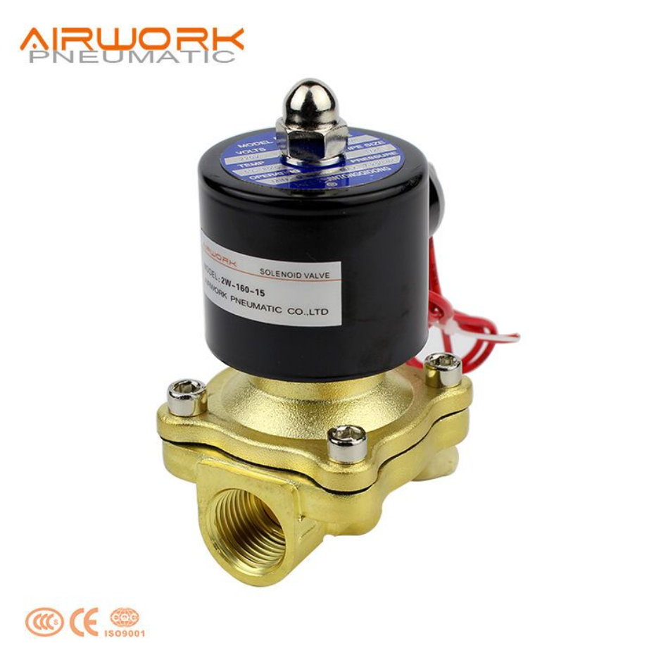
Jinzhi 2W Series Direct-Acting Normally Closed Fluid Control Pneumatic Valve (2/2 Way) — Suitable for Air, Water, and Non-Corrosive Fluid Control at Working Pressures Up to System Rating

Direct-Acting vs Pilot-Operated Valves

At lower pressures and smaller port sizes, direct-acting pneumatic valves operate without a minimum pressure differential requirement — the solenoid or manual actuation force is sufficient to move the valve element (spool, poppet, or diaphragm) against the opposing pressure force. As pressure increases and port sizes grow, the force required to open the valve against the pressure differential grows proportionally, eventually exceeding what a practical solenoid can provide. Pilot-operated valves address this limitation by using a small pilot valve — operated at low force by the solenoid — to control the much larger force of the compressed air itself in opening and closing the main valve element. Pilot-operated valves require a minimum pressure differential across the valve to operate — typically 0.5 to 1.5 bar — which must be available in the circuit at all times when valve operation is required.

Seal Material for Fluid Compatibility

The internal seals of a pneumatic valve are typically the component most vulnerable to chemical attack from the fluid being controlled. Standard pneumatic valves use NBR (nitrile rubber) seals suitable for air, water, and petroleum-based oils. For applications involving water at elevated temperatures, FKM (Viton) seals provide better resistance to thermal degradation. For chemical fluids such as dilute acids, bases, or solvents, EPDM or PTFE seals may be required — but these materials have different pressure and temperature ratings than NBR or FKM, and these differences must be accounted for in the valve selection. Always specify the seal material explicitly in the valve purchase specification and obtain confirmation from the supplier that the selected material is compatible with every fluid that will contact the valve in service.

Body Material for Pressure Rating and Corrosion Resistance

The valve body must be rated for the maximum system pressure with an appropriate safety factor. For standard pneumatic pressures up to 10 bar, engineering plastic bodies (typically nylon or polyacetal) provide adequate strength. For higher pressures or for applications involving fluids more corrosive than compressed air, brass, stainless steel, or aluminium alloy bodies are specified. Each material has a different maximum rated pressure — and different chemical resistance characteristics — that must be matched to the application. Aluminium provides a good combination of light weight, machinability, and corrosion resistance for general-purpose high-pressure pneumatic valves. Stainless steel is specified for the most corrosive fluid environments, particularly those involving chlorinated water, salt water, or aggressive chemical solutions.

Flow Coefficient and Port Sizing

The valve's flow coefficient — expressed as Cv (US) or Kv (European) — quantifies the valve's ability to pass flow at a given pressure drop across the valve. A higher Cv/Kv means higher flow capacity at the same pressure drop. For a given circuit, the required Cv/Kv is calculated from the maximum design flow rate and the permissible pressure drop. Selecting a valve with a Cv/Kv significantly below the required value creates excessive pressure drop, reducing the driving pressure available to the downstream actuator or system. Selecting a Cv/Kv much larger than required has minimal downside beyond a modest cost increase — oversizing a flow coefficient is a safe engineering decision, while undersizing creates a permanent performance limitation that is costly to correct after installation.
I BUILT MY SITE FOR FREE USING